
 English


Performance analysis and optimization of high-voltage energy harvesting current transformer (3)
In our previous discussion, we Analysis of Energy Extraction System Based on Gaped Core. Today, we will proceed with the optimization of magnetic core parameters.
2) .Optimization of Magnetic Core Parameters
Through the analysis in Section 1, we know that changes in magnetic core parameters can have an impact on the energy harvesting performance of CT. In order to enhance the load-bearing capacity of the energy harvesting CT and reduce the power supply dead zone, it is necessary to analyze the magnetic core parameters. Due to the fact that the size of the magnetic core is generally determined by the energy harvesting device, this section mainly analyzes and discusses parameters such as material, number of turns, and load.
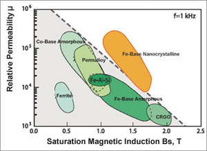
After opening the gap, the magnetic permeability of the magnetic core decreases, and the magnetic permeability of a magnetic core that originally had a higher permeability decreases more. Using Saber software for simulation, the magnetic permeability of open gap nanocrystalline magnetic cores is still two orders of magnitude higher than that of silicon steel, so nanocrystalline magnetic cores can be selected as energy harvesting cores.
2.2 Loading Analysis
Before designing turns details, it is necessary to determine the impact of the load on the power-tapping CT. When the primary current I1 varies within a certain range, changes in the load RL will affect the power-tapping performance of the CT.
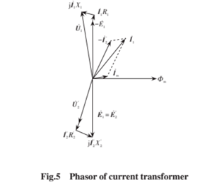
The phasor of the current transformer is shown in Figure 5.
According to Ohm's law, as the load RL increases, it will lead to an increase in the secondary voltage and maximum output power. According to power conservation, the primary voltage will increase. According to equation (6), the primary electromotive force E1 will relatively increase, and E1 is positively correlated with the magnetic fluxΦ. Therefore, the magnetic flux density B will also increase, and the magnetic core will gradually saturate; When the load RL decreases, the situation is reversed.
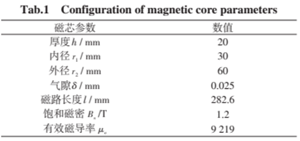
Using Saber software for simulation analysis, J-A parameters were applied to set the magnetic core material as nanocrystalline material [19], and other magnetic core parameter configurations are shown in Table 1.
The larger the air gap, the lower the magnetic permeability of the magnetic core. In order to obtain more electrical energy at a small current, the air gap should be minimized as much as possible. According to research records, the minimum achievable air gap is currently 25μm.
Due to the main consideration of reducing the lower limit of the dead zone during the design of magnetic core parameters, the primary current in the simulation was set to 5 A, the number of turns N2 in the secondary winding was set to 100, the load was set to 5-500Ω, and the sampling interval was set to 15Ω. The simulation results are shown in Figure 6 and Figure 7, respectively:
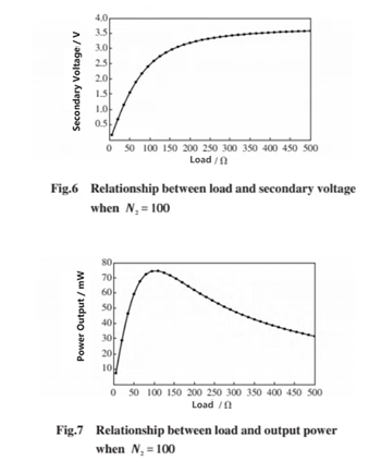
From the simulation results in Figure 6, it can be seen that as the load RL increases, the secondary voltage also increases, and the two exhibit a nonlinear relationship. When the load resistance RL increases to around 260Ω, the secondary voltage changes relatively smoothly. To ensure the normal operation of the subsequent circuit, it is necessary to avoid insufficient power supply current caused by excessive load, and also to prevent magnetic core saturation to a certain extent.
The power relationship curve in Figure 7 shows a trend of first increasing and then decreasing. At the load RL=79.51Ω, the maximum output power P2max=70.4 mW can be achieved, indicating that there is a matching resistor that can maximize the load power.
2.3 Design of secondary winding turns
The appropriate number of turns will have a significant impact on the electrical performance of CT. The excitation loss and winding impedance parameters of energy harvesting structures with different numbers of turns are also different, which in turn affects the magnitude of energy harvesting power.
According to equation (9), the number of turns N2 in the secondary winding does not affect the maximum power P2 max, but it will cause the power curve to shift because the formula contains many nonlinear variables. It is difficult to calculate the optimal number of turns from the perspective of the formula, and specific constraints are required for rough calculation. Due to the large number of samples required for the turns experiment, the experimental cost and time cost are relatively high. Therefore, using simulation analysis can provide a basis for the experiment, thereby reducing the experimental cost.
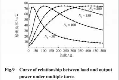
Under normal circumstances, when the primary current of the magnetic core is 5 A, the energy harvesting power has reached the minimum value that can supply some terminal devices for normal operation. Therefore, in the simulation, the primary current can be set to 5 A, and the number of turns of the secondary winding can be selected as 50, 100, 150, 200, with a load of 0-500Ω. Conduct simulation analysis and observe the changes in secondary voltage, as shown in Figure 8.
According to the simulation results, the maximum output power is independent of the number of turns, but as the number of turns increases, the maximum power point shifts to the right of the horizontal axis, which is consistent with the conclusion obtained from the equation condition of equation (9).
2.4 Determine the number of turns
In the case of a small current, the selection of the maximum power turns should be based on the size of the load while meeting the design specifications, and RL=k0N2 is sufficient.
Regarding design indicators, it is usually necessary to consider the following practical application equipment limitations and power supply requirements.
In order to achieve a higher power output for the load, the internal resistance of the winding must be lower than the resistance value of the load. Therefore, the number of turns should not be too large, otherwise its excessive internal resistance will cause significant losses, not only increasing the dead zone of energy harvesting, but also possibly causing insufficient power supply to the equipment. The maximum limit for the number of turns is:
(2) During the power supply process, the voltage must also meet the starting voltage of the hardware circuit, otherwise the circuit cannot work and cannot supply power to the load. Without considering the uneven distribution of magnetic fields in the wires, assuming the charging voltage Uset of the energy storage element is 3.7 V, it can be obtained that
In the formula, S2 is the cross-sectional area of the magnetic core.
The magnetic core parameters are shown in Table 1, with a stacking coefficient of 0.75. Given a wire radius r0=0.51 mm and a saturation magnetic flux density Bs of 1.2 T, N2 ≥ 31 can be obtained according to equations (10) and (11). For the convenience of analysis and calculation, the load can be taken as 100 Ω. Based on the simulation results in Figure 9, the number of turns of the secondary winding can be selected as 100 turns, and the load can obtain maximum power at this time.
In fact, as the current changes, the optimized number of turns corresponding to the maximum power is not a constant value. Considering that it is difficult to obtain electricity with small currents in CT, and that there is energy overflow when obtaining electricity with large currents, this optimized turn design method not only increases the power of energy extraction with small currents, but also enhances the anti saturation ability when obtaining electricity with large currents.
Categories
New Blog
For inquiries about our products or pricelist, please leave to us and we will be in touch within 24 hours.


 Call At :
Tel : +86-20-85649266
Fax : +86-20-85649263
 Email Us :
Email : derful@coilcore.com
 Address :
A402 Zhuangyuangang Industry Park, No.186 Qishan Road, Tianhe District, Guangzhou 510663
© Copyright: 2026 Guangzhou Amorphous Electronic Technology Co.,ltd. All Rights Reserved. 粤ICP备2021057165号

IPv6 network supported