
 English



Performance analysis and optimization of high-voltage energy harvesting current transformer (2)
In our previous discussion, we noted that the magnetic core adopts an open-gap design, and through optimal parameter selection, the dead-zone current is effectively reduced. By analyzing the variation patterns of load and number of turns, we employed a method combining multiple turns with parallel resistors to suppress magnetic saturation. This approach successfully addresses the challenge of stable power supply under high-current conditions, while also accommodating the design requirements for low-current operation. Today, we will proceed with the corresponding analysis.
1) . The Analysis of Energy Extraction System Based on Gaped Core
1.1 Structure of energy extraction system
In the design of current transformer (CT) energy harvesting devices, the provision of an air gap in the magnetic core serves two primary purposes:
A). Enhancing anti-saturation capability;
B). Facilitating ease of installation and maintenance.
Introduced the air gap increasing the equivalent magnetic reluctance of the core while reducing its effective permeability, thereby improving design flexibility.
The energy harvesting system is in Figure 1:
The magnetic core first captures electrical energy via electromagnetic induction. The induced alternating current is then converted to direct current through a rectifier unit, and finally regulated by a voltage regulator circuit to supply power to the load.
Given the significant fluctuations in line current, corresponding measures are implemented to ensure stable power delivery.
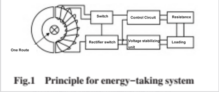
When line with low current, optimized the core parameters to reducing the power supply dead zone; while line with high current, a strategy combining multiple turns and parallel resistors is adopted to prevent core saturation and guarantee the output electrical energy effectively utilize.
1.2 Work Principle of energy extraction system
After air gap introduced, the core permeability changed, necessitating the derivation of its equivalent permeability. Neglecting the effect of fringing flux, applying Based on Kirchhoff’s second law, we obtain:
F0 = H0 l
(F0: total magnetic potential; H0: equivalent magnetic field strength; L: total length of the magnetic circuit)
Expanded expression 1 to obtain:
HFelFe + Hδ l δ = H0l
(HFe: Core magnetic field strength; Hδ: Air gap magnetic field strength; IFe: magnetic circuit length; l δ:Air gap length)
By substituting the formula μ=B/H for the definition of magnetic permeability into equation (2) and phase shifting, we can obtain:
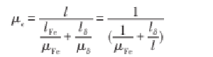
(ΜFe: Core permeability; μδ:Air gap permeability; μe: equivalent magnetic field strength; B:Magnetic flux density; H: magnetic field strength)
As the distance increasing between a certain point in space and the circuit, the magnetic field strength generated by the circuit decreases, the CT will be in an uneven magnetic field. After introduced the air gap, the magnetic core model is shown in Figure 2:
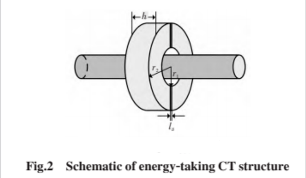
Considering the case of non-uniform magnetic field, the amplitude of magnetic flux Φ m can be obtained as:
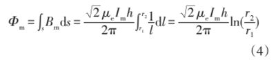
(Bm: the amplitude of magnetic flux density; Im: the effective value of excitation current)
According to the law of electromagnetic induction, the expression for the effective value of the induced electromotive force on the secondary side when the magnetic core is not saturated can be obtained:

(E2: the induced electromotive force on the secondary side; F:frequency; N2: turns of the secondary winding.)
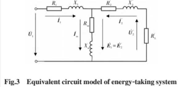
The working principle of CT is similar to that of a transformer. Based on the theory of electromechanics, the CT equivalent circuit can be obtained by deriving the transformer balance equation, as shown in Figure 3. In Figure 3, I1 and I2 represent the primary and secondary currents, respectively; U1 is the primary side voltage; U'2 is the converted secondary voltage; R1 and X1 are the internal resistance and leakage reactance of the primary winding, respectively; R'2 and X'2 are the converted internal resistance and leakage reactance of the secondary winding, respectively; Rm and Xm are the excitation resistance and reactance, respectively, reflecting the iron core loss and magnetic core magnetization degree; R'L is the converted load resistance; E1 is the induced electromotive force on the primary side; E2 is the converted secondary induced electromotive force.
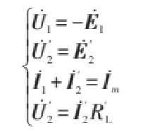
To simplify the calculation, ignoring the internal resistance and leakage reactance of the winding, and disregarding the iron core loss, the voltage balance equation can be obtained as:
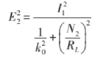
To simplify the calculation, let k0=μ e fN2 h ln (r2/r1), and simultaneously solve equations (5) and (6) to obtain:
The expression for CT output power can be derived by combining equations (6) and (7)
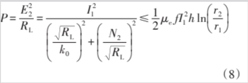
Only when RL=k0N2, equation (8) takes an equal sign, at which point there is the maximum output power, i.e

According to equation (9), the energy harvesting system has a maximum power point, and the maximum output power P2 max is positively correlated with the square of the primary current I1, the equivalent magnetic permeability μ e, the magnetic core thickness h, and the magnetic core outer diameter r2, negatively correlated with the inner diameter r1, and independent of the number of turns N2 of the secondary winding. For the expression of secondary electromotive force, there is a similar conclusion to the maximum output power P2max. Differently, when the magnetic core is not saturated, there is no theoretical maximum value for the secondary side electromotive force E2, and its value is affected by the number of turns N2 of the secondary winding.
Categories
New Blog
For inquiries about our products or pricelist, please leave to us and we will be in touch within 24 hours.


 Call At :
Tel : +86-20-85649266
Fax : +86-20-85649263
 Email Us :
Email : derful@coilcore.com
 Address :
A402 Zhuangyuangang Industry Park, No.186 Qishan Road, Tianhe District, Guangzhou 510663
© Copyright: 2026 Guangzhou Amorphous Electronic Technology Co.,ltd. All Rights Reserved. 粤ICP备2021057165号

IPv6 network supported
