
 English


Application of High Squareness Ratio Cobalt-Based Amorphous Material in Closed-Loop Current Sensors
Operating Principle

Current transformers with iron cores, anti-DC component transformers, and pulsating residual current transformers are all based on Faraday's Law and Lenz's Law. The change in magnetic flux within the transformer core induces a voltage or current in the secondary winding. Therefore, they can only detect alternating current (AC) or pulsating current. For measuring pure direct current (DC) or complex current waveforms containing both DC and AC components, special detection methods are required. A highly accurate method involves using a closed-loop fluxgate current sensor that incorporates a magnetic field probe. This type of sensor can measure currents very accurately from DC to high-frequency AC, while also providing electrical isolation between the primary circuit and the output signal.

The basic design and operating principle of a closed-loop current sensor are as follows. The primary conductor, carrying the current I (DC or low-frequency AC) to be measured, can be wound around the magnetic core bobbin (forming primary winding N1). However, the common practice is to pass the conductor directly through the center hole of the core, creating a single-turn primary winding (N1 = 1). The secondary winding, also known as the compensation coil, typically has a larger number of turns (N2).
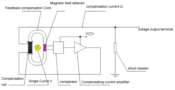
Schematic diagram of the operating principle of a closed-loop current sensor with a magnetic field probe: The magnetic flux generated by the primary current I is compensated by an appropriate current I<sub>2</sub> in the compensation coil. The cobalt-based amorphous material, used as the oscillating core within the magnetic field detector, provides the detection signal.
Any DC or AC current in the primary winding generates a magnetic flux φ in the high-permeability core. This magnetic flux is detected using a magnetic field probe placed within an air gap in the core and is nullified by adjusting the current I<sub>2</sub> in the compensation coil. The compensation current is driven and controlled by electronic circuitry. Through this closed-loop feedback process, the flux difference ΔΦ = φ<sub>p</sub> – φ<sub>c</sub> (between the primary flux φ<sub>p</sub> and the compensation flux φ<sub>c</sub>) is regulated to zero. When the equation holds true, the magnetic flux within the core is completely balanced.
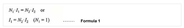
The compensation current I<sub>2</sub> is therefore proportional to the primary current I<sub>1</sub>. As the output variable of the current sensor, the compensation current I<sub>2</sub> can be measured directly or determined indirectly via the voltage drop across a measuring resistor R<sub>M</sub> connected in series.

If the magnetic flux is not balanced according to Equation 1, a current difference exists, resulting in a net magnetic flux ΔФ = Φ<sub>p</sub> – Ф<sub>c</sub> in the core. The tangential component of the magnetic field strength H is continuous within the air gap.
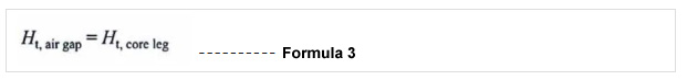
This field strength can be utilized to measure the magnetic flux in the circuit. For this purpose, a field sensing probe is placed in the gap of the core. In conventional current sensors, the magnetic field strength within the air gap is determined using a Hall probe or a magnetoresistive sensor. For example, a Hall probe provides a Hall voltage U<sub>H</sub>, which is proportional to the magnetic field strength H. However, Hall effect devices have limited sensitivity and a certain offset voltage, meaning they still produce a residual output voltage even at zero magnetic field strength H. Therefore, they require a zero-point adjustment circuit to address the offset issue.
Categories
New Blog
For inquiries about our products or pricelist, please leave to us and we will be in touch within 24 hours.


 Call At :
Tel : +86-20-85649266
Fax : +86-20-85649263
 Email Us :
Email : derful@coilcore.com
 Address :
A402 Zhuangyuangang Industry Park, No.186 Qishan Road, Tianhe District, Guangzhou 510663
© Copyright: 2026 Guangzhou Amorphous Electronic Technology Co.,ltd. All Rights Reserved. 粤ICP备2021057165号

IPv6 network supported